So it’s been coming up recently that our church media department has been buying “OpenDMX USB Dongles” for upwards of $80. I was mortified, especially after seeing this USB device, opening up the sheet metal project box and finding it to be a simple 2-stage USB to RS-485 protocol bridge with no programmable intelligence whatsoever.
During one church service, I counted out up the components in one of these boxes, along with the cost to manufacture around 12 PCBs from a 6″x6″ dual-sided copper clad (including etching and tinning my own board), dumb down the expensive 5-pin connectors to a cheaper 3-pin (technically non-compliant according to ANSI, the agency that manages the DMX-512 standard that every designer is supposed to follow). The total cost of materials, given that my labor would be, along with everything else I do for the church media department, strictly volunteer-based, came to around $20 – a quarter of what it costs them to order the pre-made one.
And talking with the church employees, the lights themselves have not been acting right, and we’re using such-and-such software from a computer to control them. Blah blah. On it goes.
Now these church employees ARE really smart. I mean, hey, they managed to set the entire network of DMX lights up, possibly with the help of a contracted expert, and have been training volunteers to program and control the network on the fly. But the terminology, and the lack of basic electronic knowledge has inspired me to make a write-up of what I’ve been learning lately.
Especially when last night I viewed THIS attrocity.
This just tells me that typical users simply don’t know what in the world they’re doing when they sink hundreds or even thousands of dollars into a system that requires the technical know-how of a digital electrical engineer.
Therefore I will see what I can do to write down my own experiences and discoveries and hopefully someone else can benefit.
Protocol
DMX is an 8-bit (technically 11-bit) digital protocol sent over a chained RS-485 bus to up to 512 slave devices. The DMX standard says that technically, only 48 devices can be chained directly together, but this can be expanded up to 512 by use of splitters and re-transmission. Also, the last device in a chain should be terminated with 120-Ohms.
This chain of devices is known as a “universe,” but can be thought of as a bus.
RS-485 is the lowest level for bit control above which all modern-day networking is performed. In short, the base protocol that connects a computer to the internet via TCP/IP is the same protocol that connects a DMX controller (sometimes software within a computer) to a chain of DMX devices.
Addressing
A single physical device can consume any number of addresses (channels) off of the bus. Each device is physically programmed (probably with a 10-pin dip switch) with a start address after which its sub-devices simply count up from that number.
The controller is automatically given address 0.
A slave device (let’s say a 4-color light with X-Y movement) is assigned in the controller with a start address and then consumes additional channels based on what it can do.
For example, an RGBW canister with X-Y movement could consume 6 channels – one for each color, one for the X stepper motor, and one for the Y stepper motor. The canister that my dad is currently working on fixing uses 7 channels. The additional channel is used for beam focusing with an additional stepper motor that moves a glass lens up and down in front of the light.
Therefore, in a controller, one can only assign devices to an address starting at 1. A second device should not be assigned to a channel that could be taken up by an already used channel, even if it is not explicitly allocated by the user, but instead has been taken up by a multi-channel device.
As in the example above, we could assign Light #1 (a 7-channel device) to Address 1. But a second light of the same type would need to be assigned to Address 8.
| Address |
Device |
Function |
| 0 |
Controller |
Main control of DMX512 bus |
| 1 |
Light 1 |
Red Intensity |
| 2 |
Light 1 |
Green Intensity |
| 3 |
Light 1 |
Blue Intensity |
| 4 |
Light 1 |
White Intensity |
| 5 |
Light 1 |
X Stepper Position |
| 6 |
Light 1 |
Y Stepper Position |
| 7 |
Light 1 |
Focus Stepper Position |
| 8 |
Light 2 |
Red Intensity |
| 9 |
Light 2 |
Green Intensity |
| 10 |
Light 2 |
Blue Intensity |
| 11 |
Light 2 |
White Intensity |
| 12 |
Light 2 |
X Stepper Position |
| 13 |
Light 2 |
Y Stepper Position |
| 14 |
Light 2 |
Focus Stepper Position |
Wikipedia’s
oscilloscope picture has been instrumental in helping me understand the digital commands required. However, it was also confusing in that I did not understand that this was a simple UART packet transmission. It was only when I opened that $80 DMX bridge and looked it over that I realized the simplicity of being able to set up a master controller with software alone.
But in short, when a DMX packet is sent, it is initialized with a “break” (logical 0 a minimum of 92us long) followed by a “mark after break” (logical 1 a minimum of 8us long). This tells the devices chained on the bus that the bytes to follow should be counted from 1 to 512 in order, and that they will execute the byte value (from 0 to 255) for the channel(s) they consume.
One can send a partial packet, as long as the break and MAB is detected to reset the bus. A packet must be sent repeatedly or devices should enter a “reset” state. So if the bus master is turned off, all devices on the bus should stop functioning, turn off, or go into an idle mode.
Addresses versus Channels
It is important not to mix up the device bus positions (addresses/channels) with the controller sliders/knobs/adjustments you assign them to. Many hardware controllers make this especially confusing by also calling the sliders “channels” as well. In a controller’s internal software, the user is supposed to first map all devices with their assigned addresses to slider channels that the controller itself defines internally.
With most controllers and controller software, it is possible to assign multiple hardware addresses to a single controller channel.
Controllers are Arbitrarily Programmed
It is important to note that, like the video above, it is often misunderstood that a physical slider on a hardware controller will not always change the intensity of a light as one would expect to change the volume on an audio mixer. What happens for each value in each channel that a device uses is up to the slave device’s manufacturer.
I had the nightmare of trying to figure out light control on a Zero 88 Fat Frog controller without first understanding that “what the device does is defined BY THE DEVICE!” That the programmer had taped over some button labels to define them as “smart lights” did not make sense because I had failed to read the user manual for the beam-shaping capability of the gobo canister hung on the rail in the ceiling. And I had no knowledge of what addresses they were assigned or what sliders they had been programmed to. Because what slider or knob or software adjustment does is defined by what address YOU assign it to control in regards to the devices connected to your bus.This brings us to…
User Interface
When I started talking with people, and reading the DMX512 standard and related Wikipedia articles, I realized that MOST hardware controllers have defined a set of manufacturers and manufacturer devices so that the setup of a controller can be easy and straightforward. Simply tell the controller that on Address 16 a Chauvet EVE E-100Z and now it knows that it has the option to access the light on Address 16 for a single-channel dimmer or on Address 16, 17 and 18 for dimmer, strobe and dimmer speed mode. Then one simply assigns Chauvet EVE E-100Z addresses to slider 1, 2 and 3, or one assigns Slider 1 to Chauvet EVE E-100Z dimmer #1, #2, and #3 along with the Chauvet DJ SlimSTRIP UV-18 blacklight wall wash unit.
But what if your software or controller doesn’t have these devices available in its repository of knowledge? If you know your device and you know your software, it should be extremely simple to just set up a general device in the configuration.
One only need tell the controller that “there is an unknown device that you should send a value to starting on Address 16 and consuming 17 and 18. These three channels you do not know what they’ll do. Therefore, simply send a value from 0 to 255 when this slider is positioned just so.”
I have a JANDS StageCL controller that I am able to play with on a weekly basis. A few months ago we went into the patch settings to see just how the DMX was set up. It turns out that someone had turned off control of a few of the white spots, and a few of the RGB washes had been shifted out to a different set of slider. This was all viewable in the patch settings. And a few of these devices were unknown to the controller’s library, but we were able assign a simple RGB device which basically told the controller that “three addresses are consumed by one device to separate red, green and blue intensity.” After that, the controller knew how to best utilize its own controls, such as color and saturation knobs and a fader that you patched the device to.
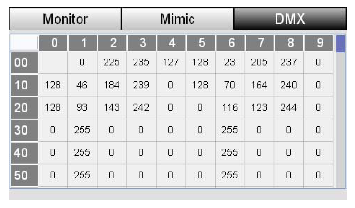
What was also interesting was the DMX monitor which simply showed the digital values that the controller was constantly pushing out to the bus. It showed nothing of the patching and slider controls. It only showed that we were sending WHATEVER was connected on address 301, 401 and 501 a value of 255. A single 255 could have been “full brightness of green” or it could have been “move x-axis stepper to 0 degrees.”
Pragmatic Programming
Yesterday I was looking at software controllers – the cheap way of setting something up. In this case, you have no hardware that buffers commands to the bus, and are relying on your multi-threaded computer to ensure that a packet is transmitted every few milliseconds to prevent the bus from going into reset/idle mode.
My dad found one called
Freestyler,which is highly rated for a freeware solution. However, he found that the device manufacturer had to be known by the software. Whether or not one could add an unknown device or define a known set of controls to the software was not researched.
I wanted something even simpler. So I found a very small utility on Sourceforge called
Lights Up! Given that this was on Sourceforge, it was also no trouble to download the CVS repository and find out how the source code was constructed (
and to fork and re-distribute it on Github).
This is the most barebones example I’ve found so far, with 48 sliders that can be assigned to any number or combination of addresses. The only requirement is that an FTDI USB-to-UART chip be registered as a virtual COM port on the PC running the software. The author assumes that this means you have to spend that horrendous $70 on the
Enttec OpenDMX USB dongle, but I found that plugging in a simple
FTDI TTL-232R-5V-PCB that we use for talking to our A2D boards would suffice. After that it’s a simple matter to re-buffer traffic from the RS-232 to RS-485 which is just a
digital driver that ensures that you can run devices on a longer distance cable at higher currents.
Looking into the Lights Up! source code, I found that by using FTDI’s C++ libraries and a intermediary “odmxusb” class library which handles the 513-byte packet, high priority threading and 30ms repeated transmission, I only need to build a 512-byte array of commands and send them into the data buffer of odmxusb. After that, everything is taken care of. That way, I can build whatever-the-heck user interface I want!
Summary
- DMX is just an RS-485 UART with an electrical interface that chains up to 512 slave devices together.
- All devices on the DMX bus read all traffic, but pick out the commands intended for them based on the byte order of the data stream and the address they are pre-programmed with.
- Because of this a fancy DMX controller, however much of a user interface layer it’s given, is at the lowest level, completely arbitrary and could be reconfigured to do Very Weird Things if the protocol is not understood.
- I want to write my own software from a point near ground-level and work my way up.
Post Views: 13
Leave a Reply
You must be logged in to post a comment.